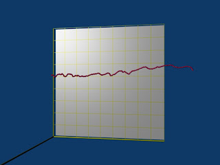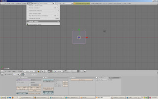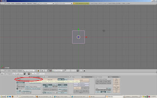
This is a quick posting. It demonstrates how to generate an x-y graph in Blender. Two functions are introduced so a curve can be generated from mesh primitives. The join method is used to combine the mesh primitives into a single object which is easy to edit and modify.
Code:
#!BPY

__doc__ = """
SimplePlottingExample.py

Example demonstrating the following techniques in Blender 2.48 to
generate a plot of x-y data:
1) Joining meshes
2) Use of the transform matrix
3) Use of material properties to control how objects are rendered
4) Delete (unlink) of objects in a scene
5) Use of cross products to generate a basis for the transform matrix
6) Using python to render an image
7) Using python to save the rendered image to disk
8) Use of Blender Vector and Matrix classes
9) Defining a function in Python
10) Using Python to parse a file

This script is executed at the command line by:
>blender -P OrientationExample.py
"""
__author__ = "edt"
__version__ = "1.0 2009/06/22"
__url__="Website, dataOrigami.blogspot.com"


##############################################################
# load the modules used in the script
import Blender
import bpy
from Blender import *
from Blender.Scene import Render
from Blender import Text
from Blender import Mathutils
from Blender.Mathutils import *
import math

##############################################################
# define function(s)

def lineSegMe(p1,p2,dia=0.1,verts=16):
 """
 This function returns a mesh which forms a line from point p1 to p2.
 The points can be passes as either blender vectors or lists of [x,y,z] points.
 This line is cylinder which goes from point p1 to p2.
 Optionally the diameter and number of vertices used to describe the line are passed.
 -------------------
 The line is formed by creating a cylinder with a length equal to the distance
 point p1 and p2. The line is then oriented using the transform matrix to rotate
 and translate the cylinder.
 """
 # use the class constructors from Blender to form vectors for p1 and p2
 p1 = Vector(p1)
 p2 = Vector(p2)

 # form a vector that points in the direction from p1 to p2
 dir = p2-p1

 # get the length of the line we want that goes from p1 to p2
 length = dir.length

 # use Mesh.Primitives.Cylinder to create a mesh for the line
 me = Mesh.Primitives.Cylinder(verts,dia,length)

 ###############
 # in the next few steps, the direction vector is used to form a basis
 #      see http://en.wikipedia.org/wiki/Basis_(linear_algebra)
 # which allows us to create a transform matrix to rotate the cylinder
 # along the direction we want. The basic idea is that the vector from
 # p1 to p2 points in the direction we want. The cylinder created by
 # Mesh.Primitives.Cylinder is oriented along the z-axis. To rotate the
 # cylinder, we  # rotate the z-axis in this direction. To completely specify
 # how to rotate, we need to provide information on how to rotate the x and y axes.
 # To define this, a matrix which is orthonormal (see http://en.wikipedia.org/wiki/Orthonormal)
 # is created from the direction vector. To create the other vectors in the
 # orthonormal basis, cross products are used to find orthogonal vectors.
 #
 # use the normalize function to set the length of the direction vector to 1
 dir.normalize()
 u = dir
 uu = Vector([0,0,1.0])
 if abs(AngleBetweenVecs(u,uu))>1e-6:
  # the direction of the line is different
  # from the z-axis
  # find the orthonormal basis
  v = CrossVecs(u,uu)
  w = CrossVecs(u,v)
  # form the transform matrix:
  #   > The first 3 rows and 3 columns form
  #   a rotation matrix because the any vertex transformed by this
  #   matrix will be the same distance from the origin as the original
  #   vertex. If this property is not preserved, then any shape formed
  #   will be skewed and scaled by the transform.
  #   > The first 3 columns in the last row define the translation
  #   applied to any vertex. In this function, the translation move the
  #   moves the end of the cylinder to the origin, then moves the end
  #   to p1.
  A = Matrix(
    [w[0],w[1],w[2],0],
    [v[0],v[1],v[2],0],
    [u[0],u[1],u[2],0],
    [dir[0]/2.0*length+p1[0],dir[1]/2.0*length+p1[1],dir[2]/2.0*length+p1[2],1])
 else:
  # the direction of the line is parallel to the z-axis
  # see the notes above on how the matrix is formed.
  A = Matrix(
    [1,0,0,0],
    [0,1,0,0],
    [0,0,1,0],
    [dir[0]/2.0*length+p1[0],dir[1]/2.0*length+p1[1],dir[2]/2.0*length+p1[2],1])

 # apply the transform to the cylinder
 me.transform(A,True)
 return me

def curve(pList,color=[1.0,1.0,1.0],dia=0.1,verts=4):
 lineMeList = []
 mat = Material.New('lineMat')  # create a new Material for the line
 mat.rgbCol = color     # change the color of the line
 for i in range(0,len(pList)-1):
  p1 = pList[i]
  p2 = pList[i+1]
  lineMe = lineSegMe(p1,p2,dia,verts)
  lineMe.materials += [mat]
  lineMeList.append(lineMe)
  # check to see if another line segment will follow
  if i<len(pList)-2:
   jointMe = Mesh.Primitives.UVsphere(verts,verts,dia/2.0)
   A = Matrix(
    [1,0,0,0],
    [0,1,0,0],
    [0,0,1,0],
    [p2[0],p2[1],p2[2],1])
   jointMe.transform(A,True)
   jointMe.materials += [mat]
   lineMeList.append(jointMe)
 return lineMeList

##############################################################
# Get rid of the lamp and cube from the default scene
scene = Scene.GetCurrent()
for ob in scene.objects:
   print ob.getName()
   if ((cmp(ob.getName(),'Lamp')==0) |
       (cmp(ob.getName(),'Cube')==0) |
    (cmp(ob.getName(),'Camera')==0)):
     scene.objects.unlink(ob)
##############################################################
# add a camera and set it up
#
camdata = Camera.New()
cam = scene.objects.new(camdata)
# use setLocation to control the position of the camera
cam.setLocation(0.9,0.5,2.1)
# use set Euler to control the angle of the camera
cam.setEuler(0*(3.1415/180),10*(3.1415/180),0*(3.1415/180))
scene.objects.camera = cam
##############################################################
# add a lamp and set it up
#
lampData = Lamp.New()
lampData.setEnergy(1.0)
lampData.setType('Lamp')
lamp = scene.objects.new(lampData)
lamp.setLocation(-2.0,2.0,5.0)
lamp.setEuler(120*(3.1415/180),30*(3.1415/180),0*(3.1415/180))
##############################################################
# load the data
#
f = open('c:\\tmp\\EmploymentPopRatio.txt', 'r')
foundData = False
xData = []
yData = []
zData = []
xLabels = []
for line in f:
 fields = line.split(',')
 if not foundData:
  for entry in fields:
   if entry == 'Year':
    # this is the header row of data
    foundData = True
 else:
  print len(line)
  if len(line)>1:
   for i in range(0,13):
    if i==0:
     print line
     print fields[0]
     year =  float(fields[0])
    else:
     month = i
     if not fields[i]==' ':
      print '::'+fields[i]+'||'
      xData.append(float(year+(month-1)/12.0))
      xLabels.append(str(year)+','+str(month))
      yData.append(float(fields[i]))
      zData.append(0.05)

print xData
print yData

# build point list
pointList = []
for i in range(0,len(xData)):
 px = (xData[i]-1948.0)/50.0
 py = yData[i]/100.0
 pz = zData[i]
 point = Vector([px,py,pz])
 pointList.append(point)

print pointList

##############################################################
# create the objects in the scene and bind materials to them
#

# form meshes for the line, join meshes so only one
#    object describes the curve
meList = curve(pointList,[1.0,0.1,0.4],0.01,8)
rooted = False
for me in meList:
 if not rooted:
  ob = scene.objects.new(me,'curveOb')
  rooted = True
 else:
  localOb = scene.objects.new(me,'localCurveOb')
  ob.join([localOb])
  scene.objects.unlink(localOb)
#
##############################
#
# create the lines for axes and a ball at the origin
p0 = Vector([0,0,0])
px = Vector([1,0,0])
py = Vector([0,1,0])
pz = Vector([0,0,1])
xMe = lineSegMe(p0,px,0.01,32)
yMe = lineSegMe(p0,py,0.01,32)
zMe = lineSegMe(p0,pz,0.01,32)
xOb = scene.objects.new(xMe,'xAxisOb')
yOb = scene.objects.new(yMe,'yAxisOb')
zOb = scene.objects.new(zMe,'zAxisOb')
originMe = Mesh.Primitives.UVsphere(32,32,0.01)
originOb = scene.objects.new(originMe,'originOb')

mat = Material.New('axisMat') # create a new Material called 'newMat'
mat.rgbCol = [1.0, 1.0, 0.0] # change its color

# attach the materials using two different techniques
#  >for the xaxis and the origin, the material is attached to the mesh by
#  by referenging the mesh from the object using
#  getData
#  > for the y & z-axis, we use the mesh reference. Since the
#  objects in the scene just point to the original mesh
#  attached to them, changing the mesh changes the object.
originOb.getData(False,True).materials+=[mat]
xOb.getData(False,True).materials += [mat]
yMe.materials += [mat]
zMe.materials += [mat]

# create a grid for the axes and place it on the x-y plane with
# use material properties to make it look like a grid
#  by only drawing vertices and edges
mat = Material.New('axisGridMat') # create a new Material called 'newMat'
mat.rgbCol = [1.0, 1.0, 0.0]      # change its color
mat.mode |= Material.Modes.WIRE   # only render edges and vertices
zGridMe = Mesh.Primitives.Grid(10,10,1)
zGridOb = scene.objects.new(zGridMe,'zGridOb')
zGridOb.setLocation(0.5,0.5,0)
zGridOb.getData(False,True).materials += [mat]
# this makes the grid appear as an outline in the Blender editor
zGridOb.setDrawType(Object.DrawTypes["WIRE"])


mat = Material.New('xyBackMat') # create a new Material called 'newMat'
mat.rgbCol = [1.0, 1.0, 1.0]      # change its color
xyBackMe = Mesh.Primitives.Grid(2.0,2.0)
A = Matrix(
 [0.5,0,0,0],
 [0,0.5,0,0],
 [0,0,0.5,0],
 [0.5,0.5,-0.05,1])
xyBackMe.transform(A,True)
xyBackOb = scene.objects.new(xyBackMe,'xyBackMe')
xyBackOb.getData(False,True).materials += [mat]
# this makes the grid appear as an outline in the Blender editor
xyBackOb.setDrawType(Object.DrawTypes["WIRE"])

#######################################
# render the image and save the image
#
context = scene.getRenderingContext()
# enable seperate window for rendering
Render.EnableDispWin()
context.imageType = Render.JPEG
# draw the image
context.render()
# save the image to disk
# to the location specified by RenderPath
# by default this will be a jpg file
context.saveRenderedImage('PlotExampleQND.jpg')

Window.RedrawAll()
#
########################################
Data Files from Bureau Labor Statistics:
Series Id:           LNS12300000
http://data.bls.gov/PDQ/servlet/SurveyOutputServlet?data_tool=latest_numbers&series_id=LNS12300000
Seasonal Adjusted
Series title:        (Seas) Employment-Population Ratio
Labor force status:  Employment-population ratio
Type of data:        Percent
Age:                 16 years and over


Year,Jan,Feb,Mar,Apr,May,Jun,Jul,Aug,Sep,Oct,Nov,Dec,Annual,
1948,56.6,56.7,56.1,56.7,56.2,57.0,57.1,56.6,56.6,56.5,56.5,56.8,
1949,56.2,56.2,56.0,55.7,55.4,55.0,55.0,55.1,55.3,54.9,55.6,55.3,
1950,55.1,55.1,55.1,55.8,55.8,56.2,56.1,56.8,56.6,56.9,56.9,56.7,
1951,56.9,57.0,57.7,57.3,57.6,57.1,57.6,57.4,57.1,57.3,57.1,57.7,
1952,57.7,57.7,57.1,57.1,57.3,57.3,57.0,56.8,57.4,56.9,57.5,57.6,
1953,57.8,58.0,58.1,57.5,57.1,57.4,57.4,57.1,56.8,56.7,56.5,55.7,
1954,55.7,56.2,55.7,55.7,55.4,55.2,55.0,55.2,55.5,55.5,55.5,55.2,
1955,55.7,55.7,55.8,56.2,56.3,56.3,56.9,57.1,57.2,57.2,57.4,57.7,
1956,57.8,57.5,57.3,57.5,57.6,57.5,57.5,57.6,57.6,57.5,57.3,57.3,
1957,57.0,57.5,57.6,57.2,57.1,57.2,57.5,56.9,57.0,56.8,56.4,56.6,
1958,55.9,55.5,55.3,55.2,55.4,55.2,55.2,55.4,55.4,55.6,55.5,55.5,
1959,55.7,55.5,56.0,56.3,56.2,56.3,56.3,56.1,56.0,56.1,55.7,56.3,
1960,56.0,56.2,55.4,56.4,56.4,56.5,56.2,56.1,56.4,55.8,56.1,55.7,
1961,55.7,55.5,55.6,55.2,55.2,55.6,55.2,55.3,55.0,55.3,55.5,55.3,
1962,55.4,55.7,55.7,55.4,55.7,55.6,55.3,55.7,55.7,55.5,55.2,55.2,
1963,55.2,55.1,55.3,55.5,55.3,55.3,55.4,55.4,55.5,55.5,55.4,55.3,
1964,55.3,55.6,55.5,55.9,56.1,55.6,55.7,55.7,55.7,55.6,55.7,55.6,
1965,55.7,55.7,55.9,56.0,56.2,56.1,56.5,56.3,56.2,56.4,56.4,56.6,
1966,56.7,56.6,56.6,56.8,56.7,56.9,56.9,57.0,57.1,57.1,57.4,57.3,
1967,57.1,57.0,56.8,57.1,57.0,57.3,57.4,57.4,57.4,57.5,57.5,57.6,
1968,57.0,57.3,57.4,57.4,57.8,57.8,57.6,57.5,57.5,57.5,57.6,57.7,
1969,57.6,57.9,57.9,57.9,57.8,58.0,58.0,58.1,58.1,58.1,58.1,58.1,
1970,58.0,57.9,57.9,57.9,57.5,57.3,57.4,57.2,57.0,57.0,56.9,56.7,
1971,56.8,56.6,56.4,56.6,56.6,56.2,56.5,56.6,56.6,56.6,56.8,56.8,
1972,56.7,56.7,56.9,56.9,57.0,57.0,57.0,57.1,57.0,57.0,57.2,57.3,
1973,57.1,57.5,57.8,57.7,57.7,58.0,57.9,57.8,57.9,58.1,58.2,58.2,
1974,58.2,58.2,58.2,58.0,58.0,58.0,58.0,57.8,57.7,57.6,57.3,56.9,
1975,56.4,56.1,56.0,55.9,56.0,55.8,56.0,56.1,56.1,56.1,56.0,56.1,
1976,56.4,56.5,56.7,56.8,57.0,56.8,57.0,57.0,56.9,56.9,57.0,57.0,
1977,57.0,57.2,57.4,57.6,57.8,57.9,57.8,58.0,58.1,58.2,58.6,58.7,
1978,58.8,58.8,58.8,59.2,59.3,59.5,59.3,59.4,59.5,59.7,59.8,59.8,
1979,59.9,60.1,60.0,59.8,59.8,59.9,60.0,59.8,60.0,59.9,60.0,60.1,
1980,60.0,60.0,59.7,59.4,59.1,58.9,58.8,58.8,58.9,58.9,59.0,59.0,
1981,59.1,59.2,59.4,59.6,59.5,59.0,59.1,59.1,58.7,58.8,58.6,58.2,
1982,58.2,58.2,58.1,57.9,58.2,57.8,57.7,57.8,57.6,57.4,57.3,57.2,
1983,57.2,57.1,57.1,57.3,57.3,57.8,58.1,58.2,58.4,58.4,58.7,58.8,
1984,58.8,59.1,59.1,59.3,59.7,59.9,59.8,59.6,59.7,59.7,59.8,59.9,
1985,59.9,60.0,60.2,60.1,60.1,59.8,59.9,60.0,60.3,60.3,60.4,60.4,
1986,60.6,60.3,60.5,60.5,60.5,60.7,60.8,60.8,60.8,60.9,60.9,61.0,
1987,61.0,61.1,61.2,61.3,61.6,61.4,61.6,61.8,61.6,61.8,61.9,62.0,
1988,62.0,62.1,61.9,62.2,62.0,62.3,62.3,62.4,62.4,62.5,62.7,62.6,
1989,62.9,62.9,62.9,62.9,62.9,63.0,63.0,63.1,62.8,62.9,63.0,63.0,
1990,63.2,63.2,63.2,63.0,63.1,62.9,62.8,62.7,62.5,62.5,62.3,62.2,
1991,62.0,61.9,61.8,62.0,61.6,61.7,61.6,61.5,61.6,61.5,61.4,61.2,
1992,61.5,61.3,61.5,61.6,61.5,61.5,61.6,61.6,61.4,61.3,61.4,61.4,
1993,61.4,61.4,61.5,61.5,61.7,61.8,61.8,62.0,61.7,61.8,61.9,62.0,
1994,62.2,62.3,62.1,62.3,62.5,62.3,62.3,62.6,62.7,62.9,63.0,63.1,
1995,63.0,63.1,63.1,63.1,62.7,62.7,62.8,62.8,62.9,62.9,62.8,62.7,
1996,62.7,62.9,63.0,63.0,63.0,63.2,63.3,63.3,63.4,63.5,63.4,63.4,
1997,63.4,63.4,63.6,63.7,63.8,63.7,63.9,63.9,63.9,63.9,64.1,64.0,
1998,64.0,64.0,64.0,64.1,64.1,64.0,64.0,63.9,64.2,64.1,64.2,64.3,
1999,64.4,64.2,64.2,64.2,64.3,64.2,64.2,64.2,64.2,64.3,64.4,64.4,
2000,64.6,64.6,64.6,64.7,64.4,64.5,64.2,64.2,64.2,64.2,64.3,64.4,
2001,64.4,64.3,64.3,64.0,63.8,63.7,63.7,63.2,63.5,63.2,63.0,62.9,
2002,62.7,63.0,62.8,62.7,62.9,62.7,62.7,62.7,63.0,62.7,62.5,62.4,
2003,62.5,62.5,62.4,62.4,62.3,62.3,62.1,62.1,62.0,62.1,62.3,62.2,
2004,62.3,62.3,62.2,62.3,62.3,62.4,62.5,62.4,62.3,62.3,62.5,62.4,
2005,62.4,62.4,62.4,62.7,62.7,62.7,62.8,62.9,62.8,62.8,62.7,62.8,
2006,62.9,63.0,63.0,63.0,63.1,63.1,63.0,63.1,63.1,63.3,63.3,63.4,
2007,63.3,63.2,63.3,63.0,63.0,63.0,62.9,62.8,62.9,62.7,63.0,62.7,
2008,62.9,62.7,62.7,62.7,62.5,62.4,62.3,62.1,61.9,61.7,61.4,61.0,
2009,60.5,60.3,59.9,59.9,59.7, , , , , , , ,
To copy the code snippets easily, see:http://dataorigami.blogspot.com/2009/06/how-to-easily-copy-code-snippets-from.html
To execute the script in Blender, see:http://dataorigami.blogspot.com/2009/06/how-to-execute-script-from-command-line.html
To work with the script in a simple IDE, see:http://dataorigami.blogspot.com/2009/04/developing-scripts-for-blender.html


